|
H21: Light, Materials and Colour
|
©
James H Nobbs
[Colour4Free]
|
When we are viewing an object or a
surface, it is the light reaching our eyes that conveys the appearance
of the surface to us. The appearance is our interpretation of
the characteristics of the light, characteristics that arise from the
interactions of the light incident on the object with the material of
the object.
The
object may absorb, scatter or reflect the light. Some types
of interaction are wavelength dependent, for example some wavelengths
of light may be absorbed more strongly than other
wavelengths. Other types of interaction may be occurring
giving rise to effects such as interference or luminescence.
|
As
an example of the many types of possible interaction, consider the
light shining onto a glossy printed layer, as illustrated in Figure
1. The light will be partially reflected at the surface,
partially absorbed and scattered by the pigments present in the ink
layer, and may be either absorbed or reflected by the underlying
substrate layer.
|
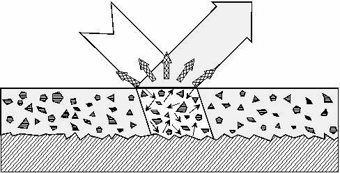
Figure 1: Interactions of a
light beam with printed surface
|
In most
cases, several effects will combine to give the overall colour
appearance of the printed surface. The most common effects
are reflection, refraction, diffraction, absorption, scattering,
interference and luminescence; each of these effects will be discussed
in the following sections.
Reflection and refraction
Reflection of light and
refraction of light occur whenever the beam travels across a boundary
between two materials that do not have the same refractive
index. At such a boundary, the incident light is partially
reflected (back from the boundary) and partially refracted (into the
body of the material), due to the change in refractive index.
The process is illustrated in Figure 2.
Boundary reflection
Reflection of light at a
boundary or a surface does not of itself cause colour.
However, in many materials it contributes towards the overall
appearance through the impression of the gloss of the
surface. The boundary reflected light has the spectral
properties of the light source, as it has not entered the material at
all. If the object is illuminated with white light, then the
gloss or boundary reflection is also white light.
The colour of the print is
arises from the light that has passed through the boundary layer and
interacted with the pigments or dyes in the ink layer. When
the print is viewed at an angle so that white gloss light from the
boundary is mixed with the coloured light from the interior,
the intensity of the colour is reduced, making the print
appear lighter and weaker than at other viewing angles.
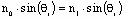
The proportion of light that
is reflected by the boundary rather than refracted into the layer is
determined by the difference in refractive indices between the two
materials (Fresnel’s law) and by the angle of incidence the light
beam makes with the boundary. For example, a boundary between
air and a high gloss print will reflect more than 4% of the incident
light.
Gloss surface
|
Boundary reflection of
light from a perfectly flat surface follows the well-known law that the
angle of incidence is equal to the angle of reflection (Figure
2). When this mirror like law applies the reflected light is
often known as the specular reflected light.
|
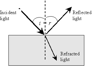
Figure 2 Surface reflection and
refraction
|
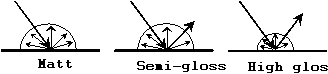
Imagine
that a beam of light is shone at a particular angle onto a very smooth
surface. The boundary reflected light would all be along a
narrow set of directions, the surface would be judged as very
glossy. An observer viewing such a surface will see, at
certain viewing angles, reflected images of the surroundings.
This gives rise to the visual impression of gloss, as illustrated by
the right-hand-side vase of Figure 3.
|
|
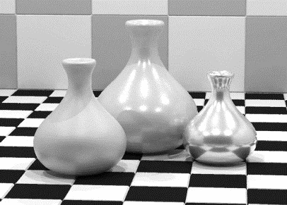
Figure
3: Reflection from different types of surface finish
|
|
Matt surface
The boundary of a very rough
surface will tend to reflect light at many different angles, because
the light meets the surface at many different angles. The
boundary reflected light is so diffuse that the observer cannot make
out images of the surroundings. The visual impression is that
of a matt surface, as illustrated by the vase on the left-hand-side of
Figure 3.
This type of appearance
characterisation is best visualised as a polar distribution, as shown
in the lower diagram of Figure 3.
Metallic effect coatings
A
further example of the use of reflection in surface coatings is that of
coatings containing metal flake pigments, such as the metallic effect
paints used on cars. The pigments used in the coatings are
generally aluminium flakes, which act as tiny mirrors within the
coating and increase the amount of white light reflected.
|
The
surfaces of the flakes are aligned parallel to the surface of the
coating layer, and so enhance reflection at the specular reflection
angle, as illustrated in Figure 4. However, reflection also
occurs from the edges of flakes, and from flakes that are imperfectly
aligned.
|
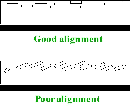
Figure 4: Flake alignment
|
The
flake reflected light, although highly directional is “spread out” over
a greater angle compared to that from the boundary reflectance of a
highgloss conventional paint. This enhances the look of the
coating, and in particular is thought to enhance the curves on a car
and make it look more sleek and attractive. On closer
inspection, it is also possible to see the individual flakes sparkling
in the light that further increases the attractiveness of the coating.
Refraction
|
When a beam of light is
shone onto a smooth, transparent surface, some of the incident light is
reflected at the boundary and some is transmitted into the
material. The direction of travel of the transmitted beam is
changed from that of the incident beam, the angle made with the normal
to the surface is called the angle of refraction, Figure 5.
|
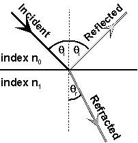
Figure 5: Reflection and
refraction at a boundary
|
Snell’s
law gives the relationship between the directions of travel.
The splitting of white light
into different colours by a prism and by certain gems arises from
refraction. The refractive index of glass, and many other
materials, changes with the frequency of the light. This
means that blue light is refracted to a different angle compared to red
light as it passes through a glass prism.
The rainbow, colours produced
by water droplets in the atmosphere, is also generated by different
degrees of refraction of the various wavelengths of light as they pass
in and out of the droplets.
Diffraction
Diffraction
is a form of interaction that all types of waves have with
objects. The effect if the interaction becomes very important
when an object or a pattern has a size or spacing of few times the
wavelength of light.
|
At
its simplest, the effect of diffraction is seen in the shadows cast by
small objects. Figure 6 illustrates the puzzle that the edge of the
shadow is not sharp but fuzzy, and the smaller the object is, the
fuzzier the edge becomes.
|
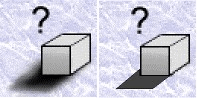
Figure 6: Diffraction causes the
edges of shadows to be fuzzy instead of sharp
|
|
The
effect is explained by considering how waves flow around and reflect
from by the objects that they meet.
In
Figure 7 a parallel beam of plane waves is shown advancing towards a
small object. The incident beam interacts with each atom in
the surface by inducing oscillations in the position of the electrons,
the oscillation causes the atom to act as an emitter of radiation.
|
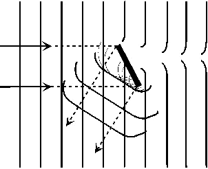
Figure 7: Reflection and
diffraction of a wave around a small object
|
The
emitted waves from each neighbouring atom have a definite phase
relationship to each other and combine to produce a short segment of a
“reflected” diffracted wavefront. This wavefront is not
sharply bounded but is spread out; the smaller is the size of the
particle then the more spread out the diffracted edge of the reflected
beam becomes.
Notice also in Figure 7 that
the edges of the transmitted beams are not sharply bounded.
The spreading out of the transmitted beams into the shadow zone causes
the edges of the shadow to be fuzzy.
A second type of diffraction
effect can give rise to colour. If the single object in
Figure 7 is replaced by a series of objects in a regular pattern, then
the “reflected” diffracted beam can be intensely coloured. A
regular spacing can cause the different wavelengths of light to be
reflected into different angles. Many spectrophotometers and
colour measuring instruments make use a device called a diffraction
grating to analyse the incoming beam of light into a series of beams of
different wavelength bands.
Another example of the
creation of a colour effect by a regular spaced pattern is given by the
surface of CD ROM computer disc. The reflected light displays an
intense colour at certain illumination and viewing angles.
Absorption
The selective absorption of
wavelengths from white light is probably the most common cause of the
creation of colour; it occurs in almost all conventional dyes or
pigments, from chlorophyll in plants to indigo in blue jeans.
Examples of the use of light absorption in creating colour might be
dyed fabrics, paint layers, pigmented plastics and printed card.
“Absorption” implies that the
light absorbed is lost as visible light; it may be converted to heat,
or other forms of energy. This conversion may be made in
several ways; the most common involves absorption of light energy by
molecules to excite electrons into a less stable (higher energy)
arrangement within the molecule. The electrons quickly fall
back to their original, stable arrangement, the molecule dissipating
the extra energy as heat.
A system will only absorb
light of particular wavelengths (the absorption band of that system), which correspond exactly
to the amount of energy needed to promote the electrons
involved. The absorption band may be wide, however, due to
the constantly changing vibrational energy of the molecules involved
changing the amount of energy needed for promotion.
Only those substances that
absorb light, radiation in the visible region of the electromagnetic
spectrum, (380 to 730 nm) appear to be coloured.
Transparent materials
A material is called
transparent if it does not contain any particles or discontinuities
that will scatter the light. Examples of coloured transparent
materials are coloured solutions and the inks used in the
four colour printing process.
The
simplest case to consider is that of a transparent, coloured material
as illustrated in Figure 8. There are many coloured,
transparent liquids where the light absorbing material is in solution;
lager beer is a good example. In the case of a printed layer,
if no scattering is occurring within the ink, then the light is
refracted on entering the coating layer and selectively absorbed by the
coating material. The remaining light is then reflected by
the substrate as in Figure 9. The emerging light beam has
passed through the coating thickness twice and therefore has twice the
chance to be absorbed.
|
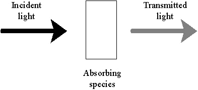
Figure 8: Selective absorption
of light by a transparent, coloured material
|
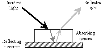
Figure 9: Passage of light
energy through a transparent coating
|
In
Figure 8 and Figure 9, the coloured material is absorbing some of the
light incident on it, and transmitting the remainder. If we
consider the spectral distribution of the intensity of the incident and
transmitted light beams, that is, the light intensity at each
wavelength through the visible spectrum, we might expect to see
something similar to Figure 10.
|
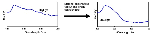
Figure 10: The effect of
selective absorption on the spectral energy distribution
|
It is
more usual to consider absorption in terms of the relative amounts that
have been transmitted or absorbed, rather than the light
intensities. In other words, we would plot the % ratio of the
intensity of the transmitted (or absorbed) light to intensity of the
incident light, as in Figure 11.
|
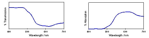
Figure 11: Typical plots of
transmission and absorption
|
The
hues of the transmitted colours due to absorption bands centred on
particular wavelengths are given in Table 1. The colour will
also depend on the width and profile of the absorption band.
A wide absorption band may give duller colours as a wider range of
wavelengths is being absorbed. For example, dull olive and
brown shades require absorption almost throughout the visible
spectrum. However, a very thin absorption band may result in
rather pale colours, even if the extinction coefficient is high.
Table 1: Hues of the absorbed light
and the transmitted light
|
Wavelengths
absorbed
|
Hue
of absorbed light
|
Hue
of transmitted light
|
|
400
- 440 nm
|
Violet
|
Greenish
yellow
|
|
400
- 500 nm
|
Blue
|
Yellow
|
|
460
- 500 nm
|
Greenish
blue
|
Orange
|
|
400
- 620 nm
|
Bluish
green
|
Red
|
|
480
- 520 nm
|
Green
|
Magenta
|
|
560
- 700 nm
|
Orange
|
Turquoise
|
|
600
- 700 nm
|
Red
|
Bluish
green
|
If the
profile of the absorption band is very steep and sharp, the colour is
likely to be very pure as light of other wavelengths is transmitted
easily. The absorption “baseline” often gives a good
indication of the purity of the transmitted light.
Scattering
of light
|
Scattering
describes any process that changes the direction of the light and is
usually associated with the interaction of light with small particles,
as illustrated in Figure 12.
|
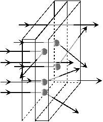
Figure 12: Change of direction
by scattering
|
|
In
fact, any change in the refractive index over a small region will cause
scattering. Air bubbles within a liquid or a solid will also
cause scattering and, in the case of beer, is the cause of the white
appearance of the froth at the top of the glass, as shown in Figure 13.
|
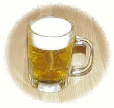
Figure 13: Transparent (beer)
and opaque (froth) forms of a liquid
|
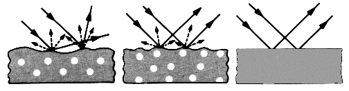
The
appearance of a material depends on the extent of scattering of the
light and adjectives such as transparent, translucent, turbid and
opaque are associated with the perceived degree of
scattering. For a colourless material, the degrees of
scattering are approximately:
|
Transparent,
|
none
of the transmitted light has been scattered
|
|
Translucent,
|
of
order of 10% of the transmitted light has been scattered
|
|
Turbid,
|
of
order of 50% of the transmitted light has been scattered
|
|
Opaque,
|
no
light is transmitted through the material
|
The
larger the difference between the refractive indices of the particles
and the surrounding medium then the stronger is the scattering
effect. For this reason, inorganic pigments, which often have
high refractive indices, tend to scatter light much more effectively
than organic pigments. Organic pigments often have refractive
indices of about 1.5, similar to that of the medium in which they are
used. Therefore, printing inks that contain organic pigments
can be almost completely transparent.
Relatively large particles
such as pigments, more than about 2.0 μm
in dimensions, scatter light by the reflection and refraction of the
light. Relatively small particles, less than about 0.3 μm
in dimensions, scatter by diffraction of the light.
The scattering of light gives
rise to one of the most common colours in the natural world - the blue
of the sky. The sky is not “blue” in the sense that other
wavelengths of light are absorbed. The sky is blue because
blue light is scattered more effectively by very small particles than
light of longer wavelengths.
|
During
the daytime, when the sun is high in the sky, the blue light reaching
our eyes (unless we look directly at the sun, which looks yellowish)
has been scattered by interaction with tiny particles in the
atmosphere. At sunrise and sunset, when the sun is low to the
horizon, we see more of the non-scattered light and the sky appears red
(Figure 14).
|
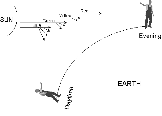
Figure 14: Blue sky and red
sunset
|
Lord
Rayleigh was the first to explain light scattering by very small
particles. He determined that the intensity of scattering
varies in three ways:
- directly with the intensity of incident light
- directly with the average volume of scattering
particles
- inversely with the fourth power of the
wavelength of incident light.
It is the third relationship
that gives rise to the different scattering power of particles to blue
light compared to red light. Very small particles (less than
about 300 nm in diameter) will scatter blue light (wavelength 400 nm)
over ten times as more strongly than red light (700 nm).
An even more spectacular
illustration of atmospheric scattering is a rainbow, caused by
scattering, (by refraction) of sunlight by very fine water
droplets. Each wavelength of light is scattered to a
different extent and so the familiar spectrum of colours is seen.
Opaque materials
When a material contains a
large amount of pigment, or a coating layer is thick enough, none of
the incident light will penetrate through the material or the coating
layer. The spectrum of the light reflected from an opaque
layer is determined by the absorption and the scattering properties of
the components in the material and does not change very much with the
thickness of the material. Another property of an opaque
material is that the addition of a transparent, colourless diluent to
the material will not change its appearance.
For an
opaque material, the fraction of the incident light reflected at each
wavelength is determined by the ratio of the absorption coefficient to
the scattering coefficient and not on their absolute values.
|
Figure
15 illustrates the paths that photons might take in an opaque,
pigmented material. The figure was obtained by using a
computer program to simulates the interactions of an incident light
beam with a layer composed of a clear medium, a white pigment and a
coloured tinter pigment.
|
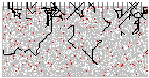
Figure 15: Simulated photon
paths, opaque layer
|
Photons
were “fired” at the top surface of the layer and when the photon
encounters a particle, a random number generator is used to decide
whether the photon is absorbed or scattered by the particle.
The figure shows the paths obtained when 30 photons were fired at the
layer.
Interference
Interference
effects are responsible for the iridescent colours seen in soap
bubbles, in oil droplets and in the wings of many insects.
The basis of this effect is the interaction between beams of light
having the same wavelength and travelling in the same direction.
|
The
oscillating electric fields can interact with each other, causing
either constructive reinforcement or destructive cancellation (Figure
16).
|
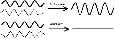
Figure 16: Constructive and
destructive interference
|
In order for interference to
occur, the oscillations of the electric fields involved must be exactly
in phase with each other (reinforcement) or 90° out of phase
(cancellation). Ordinary white light is fairly disordered
with respect to phase, the phase of the wave jumps forwards and
backwards every few cycles and this is known as non-coherent
light. Because of this, interference rarely occurs for
ordinary light, except under specific circumstances.
Thin film interference
|
A
common situation when interference can occur is in thin films or layer
structures, as illustrated by the colours shown in the reflections from
the surface of soap bubbles, Figure 17.
The
intensity of the incident light is split at the surface of the film,
and part is reflected from the top boundary and part is refracted into
the material. The refracted beam passes through the layer and
is internally reflected at the lower boundary. The back
reflected beam passes back through the upper surface boundary and then
has the same direction as the top boundary reflected beam.
|
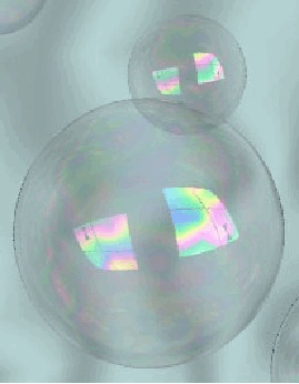
Figure 17: Interference creates
colours in reflections from a soap bubble
|
|
This
is illustrated in Figure 18. Thin-film interference colours
can be seen even with non-coherent incident light so long as the film
is very thin.
In Figure 18 it is
clear that the lower boundary reflected beam has travelled further
through the material than the top boundary reflected beam.
|
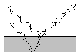
Figure 18: Interference due to
reflection at top and lower boundaries of thin film of material
|
Thus, at
a particular angle of viewing the two beams leaving the surface of the
material will be out of phase with each other and interfere
destructively, such that no light emerges. The light energy
is not being lost, merely re-distributed to take part in constructive
interference at another angle of viewing. For a particular
wavelength of light, we can calculate the angles of viewing at which
constructive interference will occur and a bright colour will be seen.
Interference
pigments
Interference pigments make
use of this effect to generate colour from white light. The
pigments are generally composed of platelets of natural mica coated
with a thin layer of a transparent metal oxide (such as titanium
dioxide, chromium (III) oxide or iron (III) oxide), Figure 19.
When
incorporated in a coating, the platelets are aligned such that they
behave as a multiple layer system, Figure 20.
|
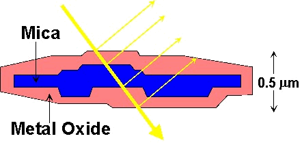
Figure 19: Cross section of a
particle of a mica based interference pigment
|
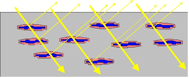
Figure 20: Mica platelets
aligned in a coating layer
|
The
thickness of the metal oxide layer is closely controlled such that
interference will occur when the coating is viewed at particular
angles. These coatings thus exhibit what is known as “colour
flop”, whereby the colour seen changes with the angle at which the
surface is illuminated and viewed, as shown in Figure 21.
|
|
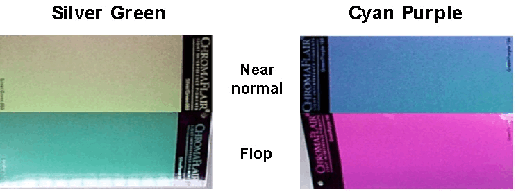
Figure 21: Near normal and Flop
colours for coatings containing Chromaflair pigments
|
Luminescence
The
term “luminescence” covers the generation of light by the conversion of
other forms of energy. The stimulus energy may be supplied in
many ways such as by heating (thermoluminescence), by the action of an
electrical energy (electroluminescence) or by irradiation with visible
or ultra-violet light (photoluminescence).
|
The
most familiar type of luminescence is probably
photoluminescence. Radiation of a relatively short wavelength
(high energy) is absorbed by a material and after a short time; the
energy is emitted as light of a longer wavelength (lower
energy). The energy changes undergone by a molecule are
illustrated in Figure 22. The residual energy is converted to
heat.
|
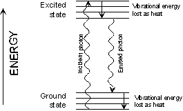
Figure 22: Loss of energy by
photoluminescence
>
|
For
example, the optical whitening agents used in textiles and in
detergents, absorb ultra-violet radiation and re-emit the energy as
blue light (the “blue-whitener”). Luminous paints act in a
similar way.
Photoluminescence may be
split into fluorescence and phosphorescence. The distinction between these two
is that emission by fluorescence occurs virtually immediately after the
energy is absorbed. The light emission by phosphorescence is
usually delayed and emission by excited molecules may persist for some
time after the removal of the stimulus radiation.
Creation of Colour
It is clear from just looking
around that most coloured objects can be classed as “reflective” or
“surface colours”. They appear coloured because of the
interaction of the white light shining onto their surfaces with the
atoms and molecules within the surface. The majority of
materials produced by the printing industry are surface colours and
understanding the creation of surface colours is the topic of this
section.
The
majority of materials produced by the surface coatings industry and the
printing industry create colour by the action of the dyes or pigments
incorporated into the printing ink or the coating material.
|
The normal situation of
viewing an object is illustrated in Figure 23. A “white”
light source is used to illuminate the object.
The colorants within the surface of the object
interact with the incident light and a proportion of the light is
reflected by the surface towards the eyes of the observer.
The observer perceives the colour of the surface.
|
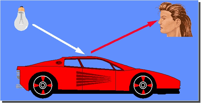
Figure 23: Creation of colour by
the interaction of light with an object and an observer
|
Light absorption and reflection
When
white light is shone onto a white piece of paper, the surface reflects
some of the light towards the eye. The cone sensors in the
eye produce a balanced set of three visual signals, from the long,
medium and the short wavelength sensitive cones. The signal
is transmitted to the brain of the observer where the brain interprets
the balanced signal as “white”.
|
When
white light is shone onto a print layer or a coating layer the pigments
or dyes that are present absorb energy at some of the wavelengths in
the incident light. The light at the remaining wavelengths is
reflected back by the substrate or by any highly scattering “white”
pigments that may be present. The process is illustrated in
Figure 24.
|
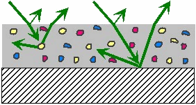
Figure 24: Absorption and
scattering of light by a printed surface
|
The
light reflected from the surface will enter the eye however, however
some of the wavelengths are weakened or missing compared to "white"
light, as a result the set of signals sent to the brain is no longer in
balance. The brain interprets the unbalanced signal as a
coloured surface.
|
Conventional
pigments create colour by absorbing light within a band of wavelengths
within the visible spectrum. The creation of various colours
can be understood by considering the absorption and reflection of light
within, a blue band (band 1), a green band (band 2) and a red band
(band 3). The three bands of wavelengths shown in Figure 25
|
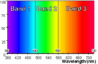
Figure 25: Blue, green and red
wavelength bands>
|
To
appear coloured, a material should mainly absorb light from wavelengths
within one, or at most two of the bands shown in Figure 25.
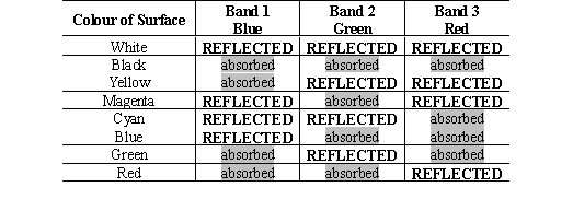
Table 2 illustrates the way in which the colour is created by selective
absorption within the three wavelength bands. If the material
absorbs in none of the bands then it will appear white. If it
absorbs equally at wavelengths spread evenly through all three of the
bands then it will appear grey or black.
Table 2: Surface colours and light
absorbed
Reflectance spectra
Red
surface
|
A
red object appears red because the material absorbs most of the light
with wavelengths in the blue band (1) and in the green band (2), only
the wavelengths in the red band (3) are reflected into the
eye. This is illustrated in Figure 26 for a red surface with
the CIE specification
L*
= 60.0, a* = 50.0, b* = 15.0.
|
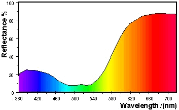
Figure 26: Reflectance
spectrum of a red surface
|
Green surface
|
A
green object appears green because the material absorbs the light with
wavelengths in the blue band (1) and in the red band (3).
Only the wavelengths in the green band (2) are reflected into the
eye. This is illustrated Figure 27 for a green surface with
the CIE specification
L* = 70.0, a* = -50.0,
b* = 10.0.
|
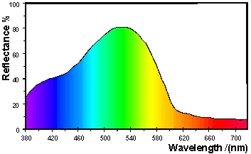
Figure 27: Reflectance spectrum
of a green surface
|
Blue
surface
|
A
blue object appears blue because the light with wavelengths in the
green band (2) and red band (3) are mostly absorbed by the material and
only the wavelengths in the blue band (2) are reflected into the
eye. This is illustrated in Figure 28 for a blue surface with
the CIE specification
L* = 70.0, a* = -10.0,
b* = -35.0.
|
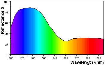
Figure 28: Reflectance spectrum
for a blue surface
|
|
H21: Light, Materials and Colour
|
©
James H Nobbs
[Colour4Free]
|